top of page

Writing Shaders in Unity can seem like a daunting task. This page is here to help you discover all the ins and outs of writing shaders in Unity3D.
What is a Shader?
What Is A Shader
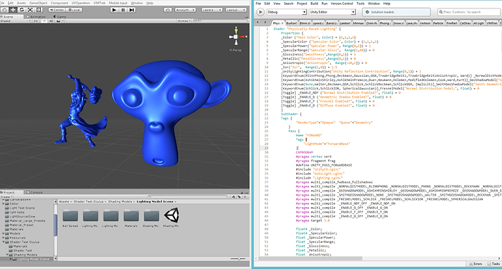
Think of Unity shaders as though they were miniature programs run specifically on a GPU. The purpose of a shader in Unity is to provide the graphics card with instructions on how to render a specific pixel on the screen. If you are familiar with programming on any level, it may help to think of shaders as classes that contain several specific functions, which we call programs. In Unity, the two main "programs" are the Vertex and the Fragment (also known as the Pixel) programs. In order to understand shaders, and how to write them in Unity, it is important to understand everything possible about these two programs. Below is an example of a Unity Shader, which we will break down and explain in more detail later on.
Vertex Programs
Vertex programs are run once for each vertex sent to the GPU. The purpose of the Vertex Program is to transform each vertex's 3D position to the 2D Coordinate at which it appears on the screen. By transforming this vertex into 2D space, we can accurately sample texture coordinates, movement, lighting and color. The output of the vertex shader goes to the next stage in the pipeline, which in most Unity Shaders is the Fragment program.
Fragment Programs
Fragment, or Pixel, programs are run for each pixel in screen space that an object inhabits. This means that Fragments can sometimes render behind other Fragments, in what we call Overdraw. This ideology is very important, and we will touch on this in some length later.
Fragment programs receive their input from Unity. The data that comes into a Fragment program is interpolated data from multiple Vertex programs. The Fragment program uses this interpolated data to accurately sample texture maps and calculate information about the surface of the model. This information typically relates to color and lighting. The output of the fragment program most commonly returns a single color value to be rendered onto the screen, however more complex inputs and outputs are possible.
In Unity there are specific ways to structure your shader code. We will go over the main pieces that make up a shader in Unity below:
Shader Structure In Unity
Shader Structure Within Unity
The Shader command contains a string with the name of the Shader. You can use forward slash characters “/” to place your shader in sub-menus when selecting your shader in the Material inspector.
The Properties block contains shader variables (ie. textures, colors etc.) that will be saved as part of the Material and displayed in the Unity Material Inspector.
Properties blocks have a very specific structure that is easy to follow, see below:
The structure for a material property is as follows :
A Shader can contain one or more SubShaders, which are primarily used to implement shaders for different GPU capabilities.
Tags are very important in Unity. For a complete list of tags, and a detailed description of their uses, check out Tags.
Each SubShader is composed of a number of passes. Each Pass represents an execution of the Vertex and Fragment code for the same object rendered with the Material of the Shader. Many simple shaders use just one Pass, but shaders that interact with lighting might need more, depending on the rendering mode of Unity (ie. Forward vs Deferred, etc.).
These keywords surround portions of Cg/HLSL code within the Vertex and Fragment Programs. Below is an example of the above structure in action within Unity.
Unity #pragma Directives and Include Files
Many times it is important to define specific shader functionality or files to include. For more information, please check out Multi-Compile Directives and Include Files as well as Shader Targets. Below is an example of #pragma directives in action, as well as included files and multi-compile directives.
The key takeaways you find here are:
These directives are extremely important. They define the functions that represent the Vertex and Fragment programs. Below we will discuss how to build the Vertex and Fragment programs that are referenced by this shader pass.
Writing Vertex Programs
Writing Vertex Programs In Unity
The first step to writing vertex programs in Unity is to familiarize yourself with the appropriate Unity defined variables.
Unity Defined Variables/Semantics
Unity defines certain variables that can be important to reference in your Vertex Program. Check out these Unity Variables, and the following variables that I have explaned below in detail:
POSITION - float4
This variable is the position of the vertex relative to the mesh. Operations can be done on this variable to determine things like world space position, and more importantly screen space position.
SV_POSITION
This semantic is one of the more important output variables of the Vertex Program. This variable designates the final “clip space” position of a vertex so the GPU knows where on the screen and at what depth to rasterize it. This variable is always a float4, and must always be computed and output by the vertex program.
NORMAL - float3
This variable designates the "Normal Direction" of the vertices. If you aren't familiar with normals here is a good explanation on Normals.
TANGENT - float4
The Tangent represents a perpendicular direction to the Normal. This typically is not any random perpendicular direction, but a specifically defined direction. This is most commonly used to compute biTangents and tangent space normals for a surface.
TEXCOORD0 - float2
This variable is specifically used by Unity to define UV space 0.
TEXCOORD1 - float2
This variable is specifically used by Unity to define UV space 1, commonly used for lightmap uvs.
Defining Custom Variables
In addition to the Unity defined variables, you do have the power to define custom variables using the semantics described below.
TEXCOORD#
Besides TEXCOORD0 and TEXCOORD1 unity allows you to define a variable with a
TEXCOORD# semantic. The TEXCOORD semantic is used to indicate arbitrary high precision data.
COLOR#
Similar to TEXCOORD unity allows you to define a variable with the COLOR# semantic. This semantic is used to indicate low-precision 0..1 data.
Vertex Program Structure
Now that we've gone over some variables and semantics, lets cover the structure of the Vertex Program in Unity.
In the code block above I have written a specific struct that creates variables that Unity writes the appropriate values into. This is done by using the appropriate syntax, which unity will see and assign the representative value. Creating this struct is important for creating the Vertex Program.
This Struct is the struct that will define our Vertex Program. It is created to hold the variables we actually want to reference later. The previous struct contains the important information we can use to calculate and set these values, but the previous struct will not be referenced again after the Vertex Program.
This is the actual Vertex Program. Let's look at this line for line, so that we can discuss each point and describe what is going on here.
Here we initialize the program, making sure that it initializes with the Unity Defined variables.
This line initializes a new VertexOutput struct. We will return this struct so that it may be used in the Fragment Program.
Here we assign the UV coordinates to our variables. Straight forward.
This line transforms the normal direction that Unity supplies (v.normal) from Object Space to World Space. When Unity processes the normal value, it does not take into account the objects rotation, so we use this function to transpose that normal into world space.
The first line above translates the tangent direction supplied by Unity into world space. We then calculate the biTangent direction from the normal and tangent direction.
The lines above calculate the world position of the vertex, and then the screen position of the vertex.
These lines calculate the fog, lighting and shadow for this vertex.
Put it all together and then you have all the foundations of a solid Vertex Program:
Writing Fragment Programs
Writing Fragment Programs In Unity
Writing Fragment Programs in Unity is a very simple task. Given an input from a Vertex Program, the Fragment Program has all the information it needs to compute a color output.
This is a very simple example of a Fragment Program in Unity. Let's break it down bit by bit.
Here we initialize the Fragment Program as a float4 with an input of our Vertex Program. When the Fragment Program is called, Unity will provide an interpolation of all of our applicable Vertex Programs. You can reference these interpolated values from inside of the Fragment Program.
Here we compute our tangent space normal direction. Given the world space normal, and our tangent and bitangent, we can transpose our normals into tangent space. This is important for using normal maps as we have above.
This line is very important, so let's break it down as much as possible:
UnpackNormal(tex2D) is used to read a normal direction from a Normal Map.
tex2D(Texture variable, TRANSFORM_TEX()) is Unity's function that allows you to read a color from a Texture Map.
TRANSFORM_TEX(texture coordinate/uvs, Texture variable) is used to transform texture by uvs and scale/bias property of Texture Map.
All together, this line above gives us a normal direction by unpacking the normal data from a texture given the uv coordinates.
The two lines above are very simple. We get the color from the main texture, and multiply that color by our _Color property. This allows us to control the color of our object by using a texture, but also a tint color.
The first line computes the direction of the current light. In Forward Rendering, a Fragment Program is run once per light, per pixel, per object. That can add up to a lot of Fragment Programs. To make sure we don't mess anything up, we sample this data in world space so we can calculate the light at the pixel. This line contains Unity Variables that are defined here.
The second line computes the attenuation of that light, using a Unity function provided by AutoLight.cginc. Attenuation is the loss of light due to transmission falloff or shadow.
The third line computes the attenuation color, which is the lights attenuation multiplied by its color.
This is simply the dot product of the light and normal, also known as NdotL. In this example, we use pure lambertian diffuse lighting to calculate the light at the pixel. For more information on lighting models, please visit Lighting Models.
The finalDiffuse variable that is calculated is a very easy method of adding light into the diffuse color. You simply multiply the pixel color by the light value at the pixel, in this case NdotL, and then multiply it by the attenuation color. This is as simple as lighting in Unity gets. Color * Light.
The second line applies fog from the scene.
The third line ends the fragment program, returning the final color to the pixel buffer.
Bringing A Shader Together
Bringing The Shader Together
After you finish your Fragment Program, there are a few steps you have to take to finish up your shader. Particularly closing the pass with:
And then closing the SubShader, following that up with a Fallback, which looks like:
This Fallback lets Unity know what to do in the event the shader code can't be run by the GPU. You should read up on Fallbacks here. Different Fallbacks have different implications, for example the "Legacy Shaders/Transparent/Cutout/" fallback family is needed to enable shadows on custom Transparent-Cutout shaders.
Optimizations
When writing shaders in Unity3D, it is important to keep in mind the performance cost of shader code. Typically, mathematical instructions are not that costly on the CPU. When running a Vertex or Fragment program, you need to remember the sheer volume of programs running each frame. Keeping this in mind, there are several important topics concerning optimizing the shader code to avoid performance implications.
Overdraw
Overdraw is a situation in which you have wasted pixels in the frame buffer. These pixels are wasted because they are drawn over by other opaque pixels, and not blended together. This means that, although you are only seeing the final fragment program that rendered a pixel, you could have potentially run thousands of wasted pixels underneath.
It is key to remember that Unity attempts to take care of this for you, using a "Z-Buffer". The Z-Buffer tests and sorts the objects pixels in a buffer, so that Unity will only render the appropriate pixels.
This would normally solve the problem, but the introduction of transparency destroys the usefulness of the Z-Buffer due to the need to blend the pixels. The more transparent objects, the higher the likelihood of overdraw. That is why it is important to optimize your shader code to make overdraw as cheap as possible.
Mathematical Functions
Certain functions can be very costly for shaders. Consider the complexity of the math, and remember the number of times that calculation could be performed (potentially millions) per frame. Here are some functions to avoid, unless absolutely necessary.
sqrt();
cos();
sin();
Loops
for();
while();
These functions and loops tend to be overkill for most realtime shaders, except in very specific controlled situations.
Summary
I hope that you have come out of this page with enough knowledge to get started playing with shaders in Unity. Generally, authoring your own shaders can be a better solution than attempting to utilize a found shader. If you have any questions regarding shaders in Unity, please comment below.
Optimizing Your Shader
bottom of page